Part one: Basic set up and transport tasks
Prerequisites
Create a new case (and project) if needed.
Step 1: Configure your strategy
You will see a warning toast to add values for two mandatory fields first.
- Click on the Build tab.
- Click on Strategy.
- Enter values for
Emergency response limitandMinimum working length. The screenshot shows some suggested values.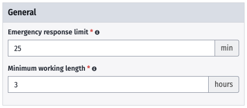
Step 2: Add your bases
You will need to create these bases in your Input Library before they appear as options in your case. Perform the following steps in the Input Library first, then add them to your case.
This case requires the following bases:
- Port: Ferrol outer harbour (ES)
- Offshore base: Ferrol wet storage (ES)
- Port: Lisnave (PT)
- Port: Esbjerg (DK)
- Port: Southampton (UK)
Follow these steps for each base:
- Click on the Bases tab.
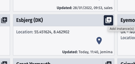
- Click Add.
- On the relevant base, click Add instance(s).
- Add weather data to your case:
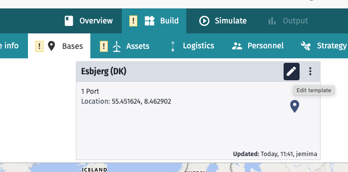
- Click on the Edit template button.
- Click on the Weather tab.
- Select a weather square for the base. Those which are coloured green have ERA-5 data pre-downloaded (so are quicker to load), but in either case it is possible to download ERA-5 weather data. Click on the square and select Use ERA5 data. This data should appear to the left.
- Click Save to exit.
- Click on the Edit template button.
- Repeat for the other bases.
Step 3: Add assets
We’re going to add 3 instances of a single asset, an 8.4 MW WTG.
- Click on the Assets tab.
- Click Add.
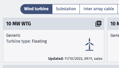
- Select an asset on the Wind turbine tab by clicking on the Add instance(s) to case button. If there isn’t an 8.4 MW asset, add a generic one.
- In the Number of Wind turbines to addinput, enter
3.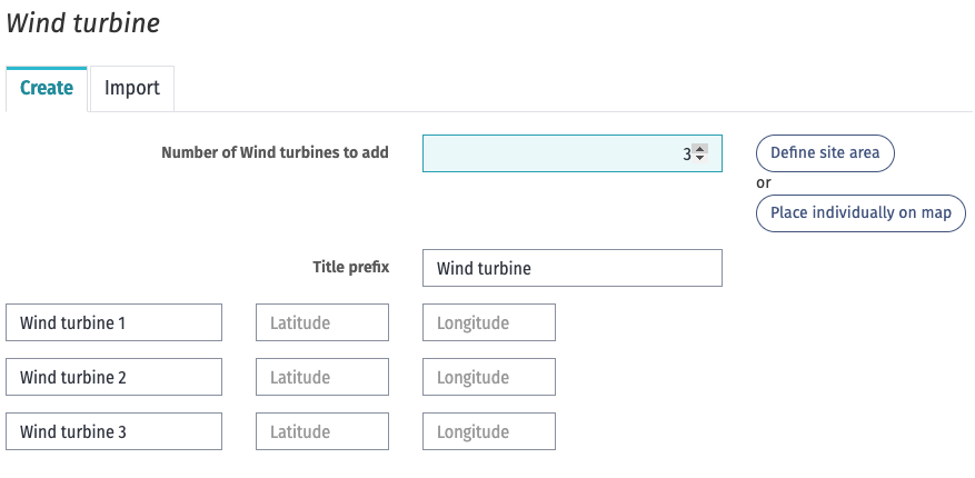
- Click Define site area.
- Click Mark corners on map.
- Mark a location off the coast of Viana do Costelo.
- Click Populate site.
- Click Next.
- Click on the Parameters tab.
- Make sure Rated power is
8.4. - Set Maximum number of technicians in asset to
5. - Click on the Weather tab.
- Select a weather square for the asset. This data should appear to the left.
- Click Add to exit.
Step 4: Add transport logistics
We need COTVs to transport the components to the assembly port (Ferrol outer harbour (ES)), so add these now. The logistics require the inputs shown in the table below.
| Component | Port | Vessel capacity |
|---|---|---|
| Nacelles | Esbjerg (DK) | 3 |
| Tower components | Esbjerg (DK) | 15 |
| Blades | Southampton (UK) | 15 |
| Floaters | Lisnave (PT) | 1 |
The following example is for the nacelles CTV:
- Click on the Logistics tab.
- Click Add.
- Click the Component transfer vesseltab.
- Add a COTV instance by clicking Add instance(s) to case.
- Rename the instance so it’s easy to identify, e.g.,
Nacelles COTV.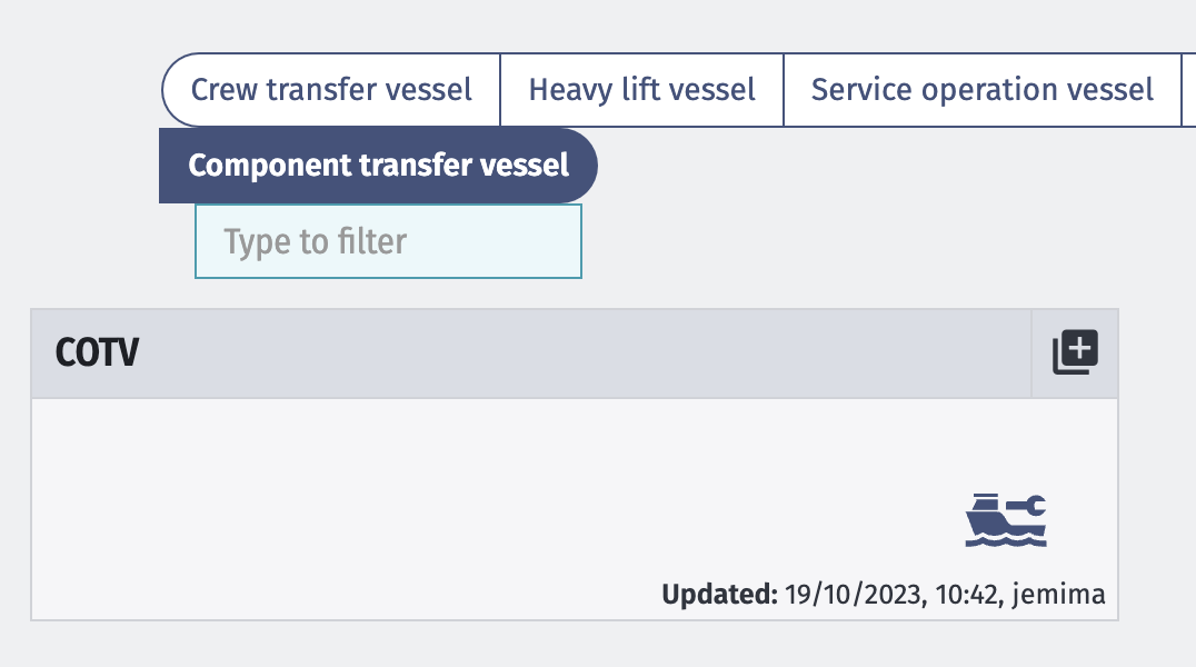
- Only
1unit is needed but add the port the vessel will start its journey from, which isEsbjergin this case. - Click Next.
- A new window will open. Change the name on the instance to
Nacelles COTVagain. - Go to the Capacity tab. Set the Maximum Capacity to
3. This means that the vessel can transport 3 nacelles each time. Minimum Capacity is the minimum number of components a vessel can carry at a time. To ensure all are transported this should usually be1.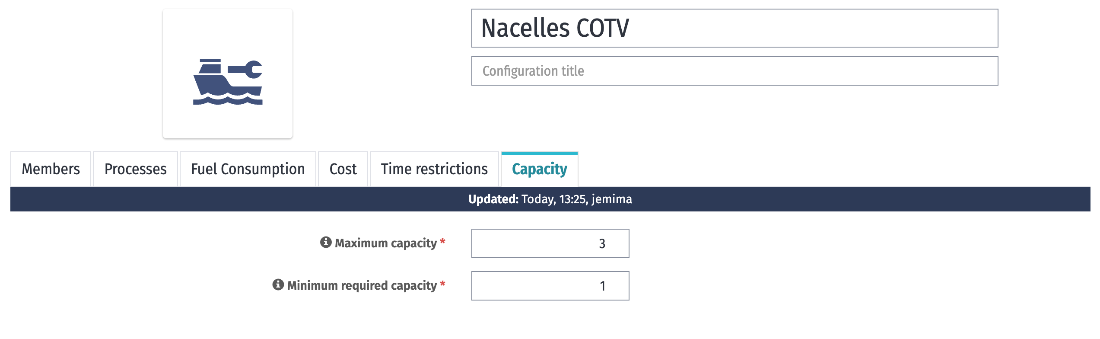
- On the Processes tab, set the transit time and restrictions for this vessel type:
2.0 - Loadout:- Duration:
4hours.
- Duration:
3.0 - Transit to Loadoff Port:- Speed:
8kn.
- Speed:
5.0 - Loadoff:- Duration:
4hours.
- Duration:
7.0 - Transit to Port:- Speed:
15kn
- Speed:
- Click Add.
Repeat these steps for the other COTVs, using the relevant ports and capacities.
Step 5: Add your first transport tasks
| Task | Loadout base | Loadoff base | Components | Component quantity |
|---|---|---|---|---|
| 1. Nacelles to Ferrol | Esbjerg (DK) | Ferrol outer harbor (ES) | Nacelle | 1 |
| 2. Towers to Ferrol | Esbjerg (DK) | Ferrol outer harbor (ES) | Tower upper | 1 |
| Tower middle | 1 | |||
| Tower lower | 1 | |||
| 3. Blades to Ferrol | Southampton (UK) | Ferrol outer harbor (ES) | Blade | 3 |
| 4. Floaters to Ferrol | Lisnave (PT) | Ferrol outer harbor (ES) | Floater | 1 |
These steps model the nacelle transport task:
- Click on the Assets tab.
- Click on the 8.4MW WTG asset.
- Go to the Tasks tab and where it says New Task write a name – e.g.,
1\. Nacelles to Ferrol. It’s generally a good idea to number the tasks so it’s easy to remember the order you intended to action them. - In the Task Type drop-down menu, select Transport.
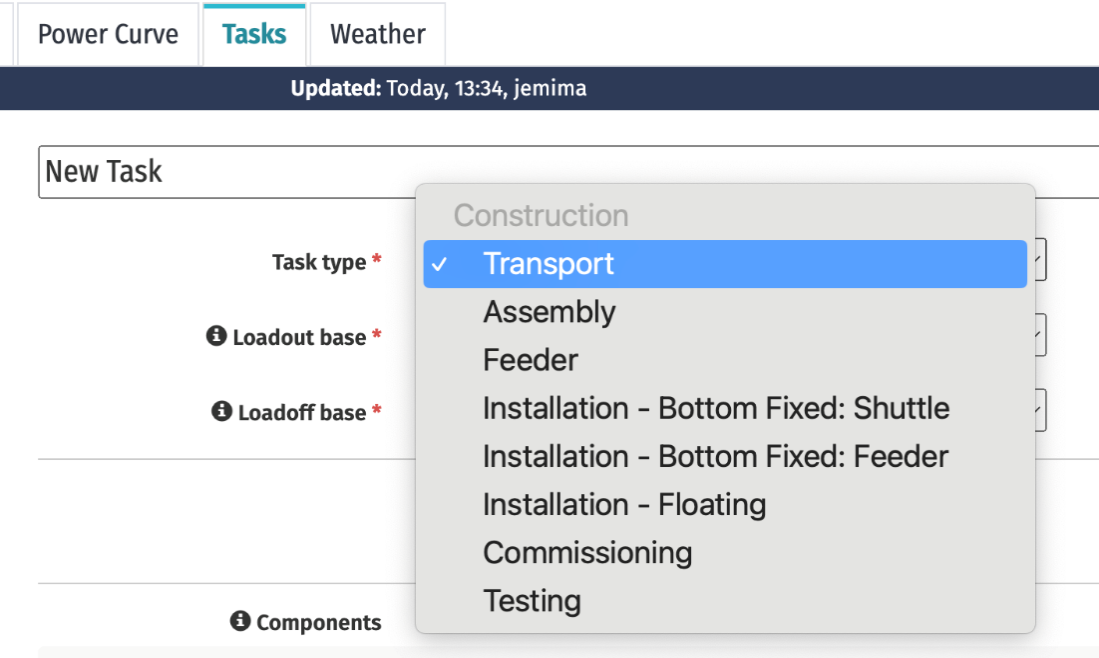
- In the Loadout base (where the components are going from) dropdown, select Esbjerg (DK).
- In the Loadoff base (where the components are going to) dropdown, select Ferrol outer harbour (ES).
- In the Componentssection, we can set what is being transported by the logistic, in this case nacelles:
- Click Add Component.
- Enter
Nacelleas the Component name. - Leave Quantity as
1. All tasks are listed per WTG, so although a total of 3 nacelles will be transported as part of the project, only 1 should be itemised here.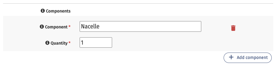
- In the Component transfer vessel dropdown, select the relevant vessel for the task, in this case the one called
Nacelles COTV. - Click Save.
Repeat the process of adding transport tasks for all the other components (on the same WTG asset), noting the quantity for each in the table above.
Step 6: Add components to the relevant bases
The next step is to ensure all the components are logged at the bases they travel to and from. This is necessary for the Inventory Management solution to work and let view the Inventory Management graph on the Output page.
When adding components to a base, you need to enter the total components for the wind farm, so 3 nacelles as opposed to 1 nacelle, in this case.
- Click on the Bases tab.
- Click on Esbjerg (DK).
- Click on the Inventory Management tab.
- Select Add componentand start typing
Nacelle. The name with the same title as you wrote before should appear. Select it (spelling is important).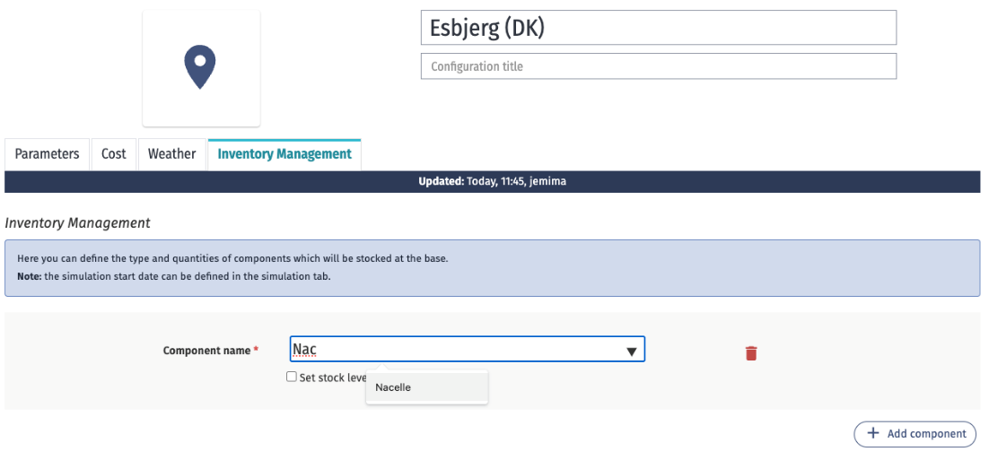
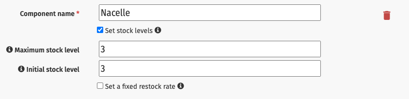
- Select Set stock levels. In this project there will only be a total of 3 nacelles, all of which start out at Esbjerg (DK). So set the following:
- Click Add component and add relevant information for
Blades. - Click Save.
Repeat this process for Southampton (UK) and Lisnave (PT). The components and values for each base are in the table below.
For Ferrol outer harbor (ES), the Initial stock level on each component should be 0 since the components will be transported to this destination, rather than starting from there.
| Base | Component | Maximum stock level | Initial stock level |
|---|---|---|---|
| Esbjerg (DK) | Nacelle | 3 | 3 |
| Tower upper | 3 | 3 | |
| Tower middle | 3 | 3 | |
| Tower lower | 3 | 3 | |
| Southampton (UK) | Blade | 9 | 9 |
| Lisnave (PT) | Floater | 3 | 3 |
| Ferrol outer harbor | Nacelle | 3 | 0 |
| Tower upper | 3 | 0 | |
| Tower middle | 3 | 0 | |
| Tower lower | 3 | 0 | |
| Blade | 9 | 0 | |
| Floater | 3 | 0 | |
| Tower assembly | 3 | 0 | |
| Floating tower | 3 | 0 |
Step 7: Run a test simulation
Your case now has enough tasks to run a simulation. Run test simulations at key points when building a case to ensure you have modelled everything correctly up to that point.
- Click on the Simulate tab.
- Choose Historical weatherand
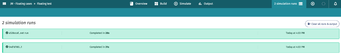
1runs (enough for a test at this stage). - Once the simulation is complete, click on 2 simulation runs in the top right corner. The runs should be green and show as
Completed. If you have any red runs, return through steps 1–6 to ensure your inputs are correct.
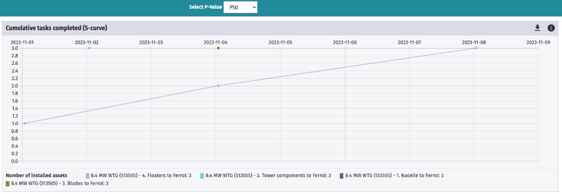
Step 8: Check your outputs
Now go to the Output tab and check your results. Do they make sense? They should look something like this, although the dates will be different for your case:
 Since you used the Inventory Management feature on your bases, you should also have access to the Inventory management graph, which can be found in the Reports section, with the selected P-value in front of the name:
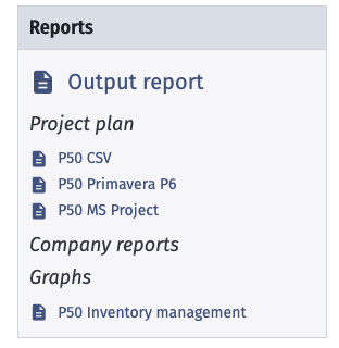 Click on it. The results should show the flow of components in and out of the various bases.